

PA Systems and Noise Predictions
Overview
The choice and alignment of your PA system determines how much sound reaches beyond the event site –and how disruptive your event feels to local residents. Loudspeakers do not radiate sound in the same way: depending on design, quantity, and setup, sound can be intentionally focused or spread widely into the surroundings.
This guide explains the most important PA types (tops/fullrange, line arrays, subwoofers), basic principles of directivity (especially in the low end), commissioning a PA system with limiter / gain staging, and options for noise predictions.
Note: Further practical measures for noise reduction can be found in the Noise Mitigation Measures guide.
Basics: PA systems
Active vs. passive loudspeakers
A common starting point when choosing a PA system is whether to use active or passive loudspeakers.
-
Active loudspeakers have an integrated amplifier and therefore need a power connection at the loudspeaker. This often simplifies setup because fewer separate devices are required. However, active loudspeakers are usually heavier and often more expensive.
-
Passive loudspeakers are powered by a separate power amplifier. The audio signal runs from the mixing console to the power amplifier and from there to the loudspeaker. These systems are usually more flexible because loudspeakers and amplifiers can be combined or replaced more easily. In addition, level limiting–depending on the setup–can often be implemented well at the amplifier stage or within the system. The downside is higher cabling and planning effort.
Which option makes sense depends mainly on the event size, the available technical know-how, and the desired setup convenience.
Beamforming and directivity pattern
For open-air sound reinforcement, this matters: sound spreads differently depending on frequency.
- High frequencies are more directional and usually easier to attenuate.
- Low frequencies, by contrast, spread equally in all directions without specific measures (omnidirectional).
The directivity pattern describes how strongly a loudspeaker focuses sound–similar to microphones. Stronger focusing helps target the event site and reduce radiation into unwanted directions.
Especially with PA systems that are very close to relevant immission locations, it can be useful to consider a directive sound reinforcement concept. In borderline cases, this can be decisive for the approval procedure / permit process and for permitted sound levels.
In the low-frequency range, achieving strong focusing is difficult. Because of the large wavelengths (at 50 Hz approx. 6.8 m), diffraction around loudspeaker enclosures and obstacles is stronger, so subwoofers often radiate approximately omnidirectionally without special arrangements. More directivity in the low end can be achieved, for example, with cardioid setups or bass arrays. By arranging and aligning multiple subwoofers, rear radiation can be reduced. Depending on the system, rear level reductions of around 10–15 dB are possible in the 40–100 Hz range. In the mid and high range, targeted focusing is much easier–often, for example, with line arrays. What matters is not only the enclosure type, but also the number, arrangement, and alignment of the loudspeakers in an array.
Note: Thoughtful PA choices can be a key step in noise reduction. More information can be found in the guide on Noise Mitigation Measures guide.
Types of PA systems
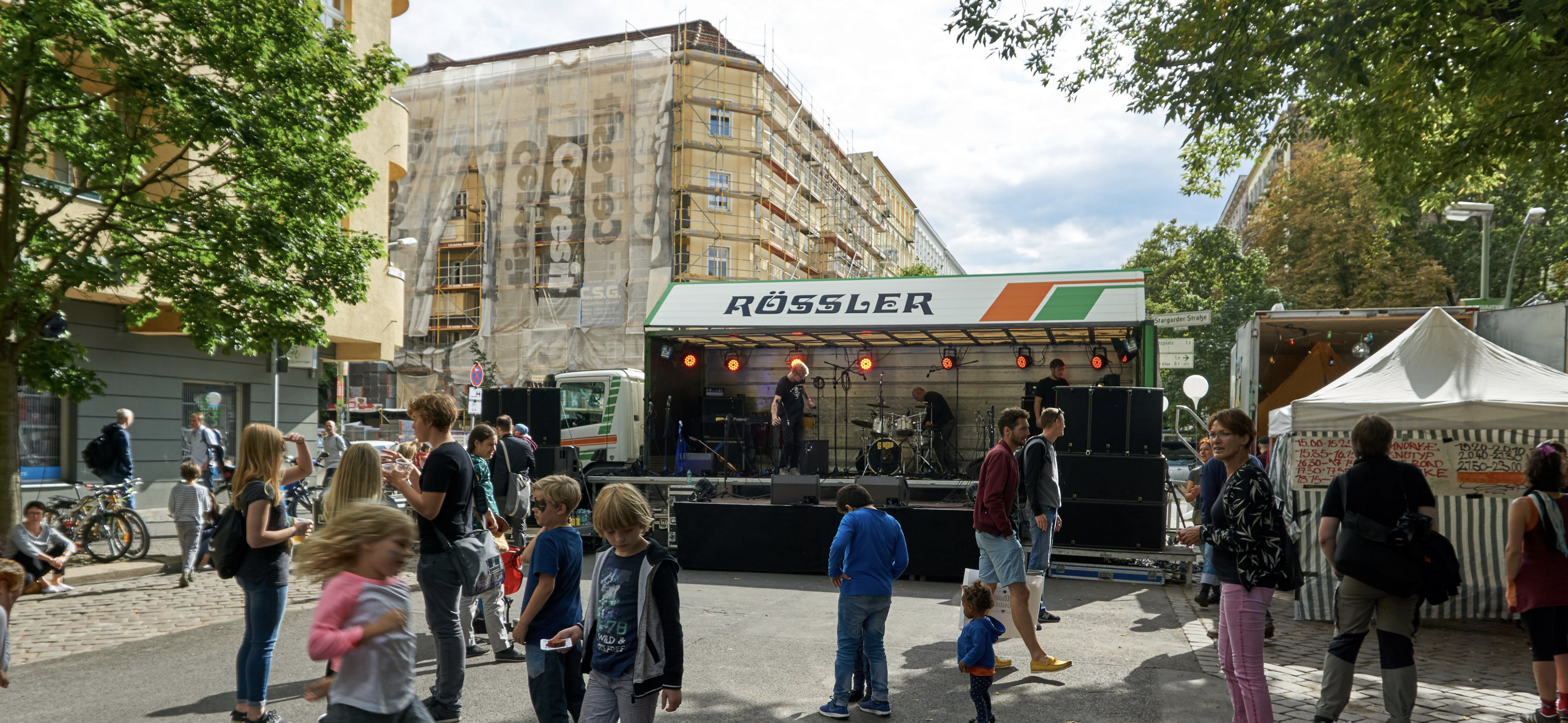
Tops and fullrange
Top speakers (sometimes simply “point sources”) typically cover the mid and high range (e.g. approx. 100 Hz to 20 kHz). They are especially important for clear speech and instrument reproduction. For speech reinforcement, intelligible mids and highs are crucial.
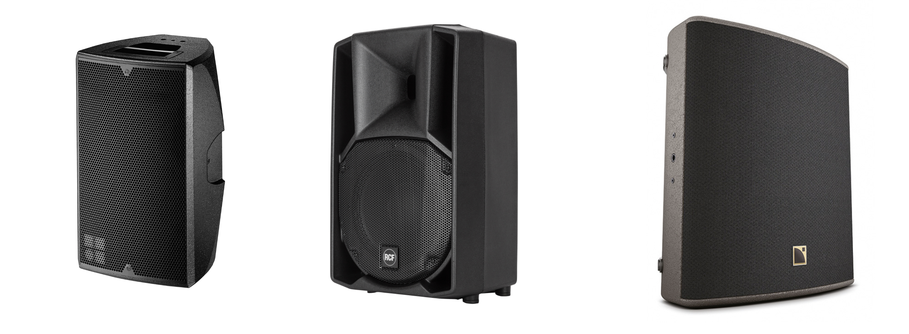
Typical top and fullrange models for open-air use, ascending by output: d&B E8, RCF ART 710-A, L-Acoustics X12 (Source: d&B audiotechnik, RCF, L-Acoustics)
When setting up, pay attention to the following:
- Alignment: Aim the loudspeakers so the audience area is covered evenly. Avoid unnecessary radiation toward nearby residential development / housing.
- Height positioning: Place tops above head height or fly them (e.g. on stands). This distributes sound more evenly and reduces the risk of overdriving the front rows.
- Coverage angle: Check the horizontal and vertical coverage angle (e.g. ). In narrow streets or courtyards, wide angles can promote reflections and level peaks. In open areas, angles that are too narrow may not cover parts of the audience.
Fullrange loudspeakers cover lows, mids, and highs. In small setups (e.g. street concerts or readings), one or two fullrange boxes are often sufficient. The same basic alignment rules apply as for tops. For larger events, however, they often reach limits–for example due to insufficient bass or an uneven frequency distribution.
Line arrays
With line arrays, multiple loudspeaker modules are stacked vertically. This allows more precise control of radiation and better targeting of sound toward the audience area. This can help reduce sound in other areas, especially for larger events. There are also compact line-array systems for smaller events. Typical models or systems are: XX
Advantages of line arrays:
- Targeted directivity: The angles of individual modules can be adjusted. This allows sound distribution to be tuned broadly or more focused on the event site.
- Modular design: Line arrays usually consist of multiple modules (often approx. 3 to 16) mounted at different angles. They are built in a column, often in a J-shape.
- More even coverage over longer distances: Line arrays can cover more distant audience areas in a more controlled way.
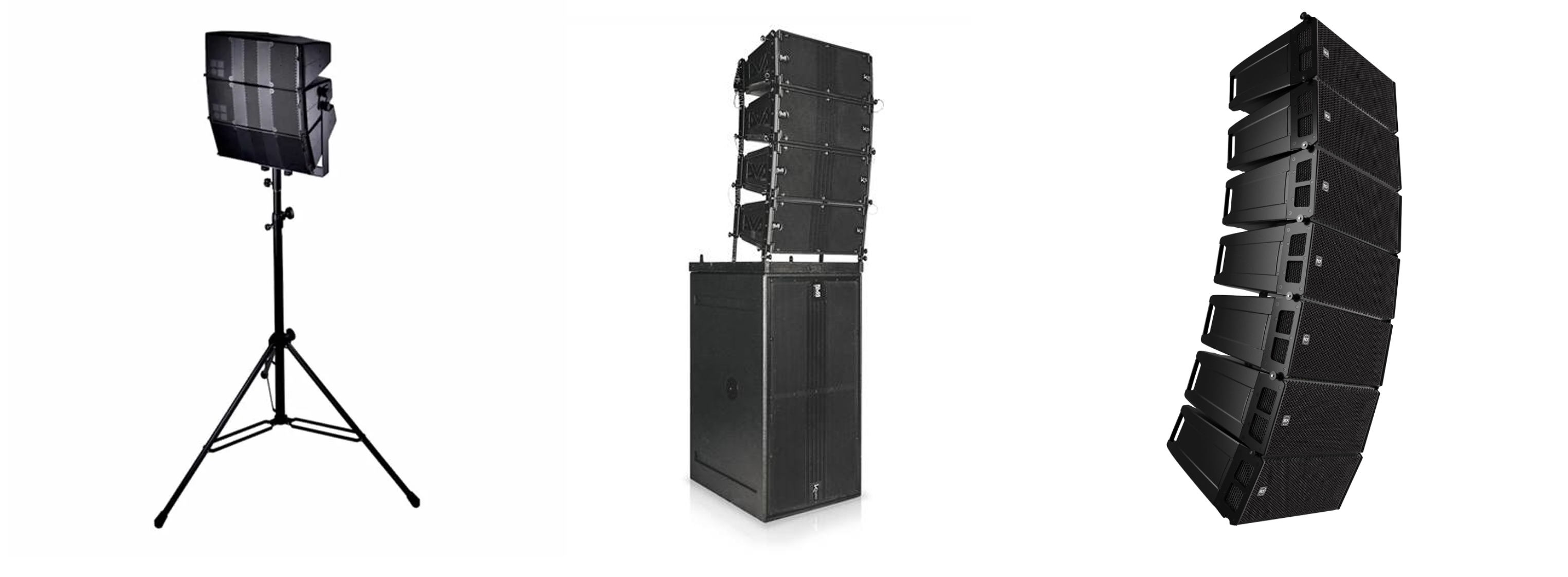
Typical line-array models for open-air use, ascending by output and size: d&B T10, dBTechnologies DVA K5, RCF HDL 26 (Source: d&B audiotechnik, dBTechnologies, RCF)
Important hints for planning with line arrays:
- Greater reach in the main radiation direction: If misaligned, more distant relevant immission locations in the main radiation direction can be affected more strongly.
- More modules mean higher directivity: As module count increases, the sound field becomes more directional over a broader frequency range. This can allow a higher level on the dancefloor at the same immission values.
- More modules mean more potential output: Even if additional acoustic output is not needed, longer arrays are sometimes used to increase directivity. In that case, level limiting can be sensible or required.
- Cost and effort: Large line arrays are more expensive to rent or purchase and often require specialist staff for setup and operation.
Subwoofers (bass loudspeakers)
Subwoofers (subs) reproduce very low frequencies (typically approx. 20–100 Hz). These frequencies are hard to focus. Without special measures, subs therefore usually radiate nearly omnidirectionally–also to the rear and sides.
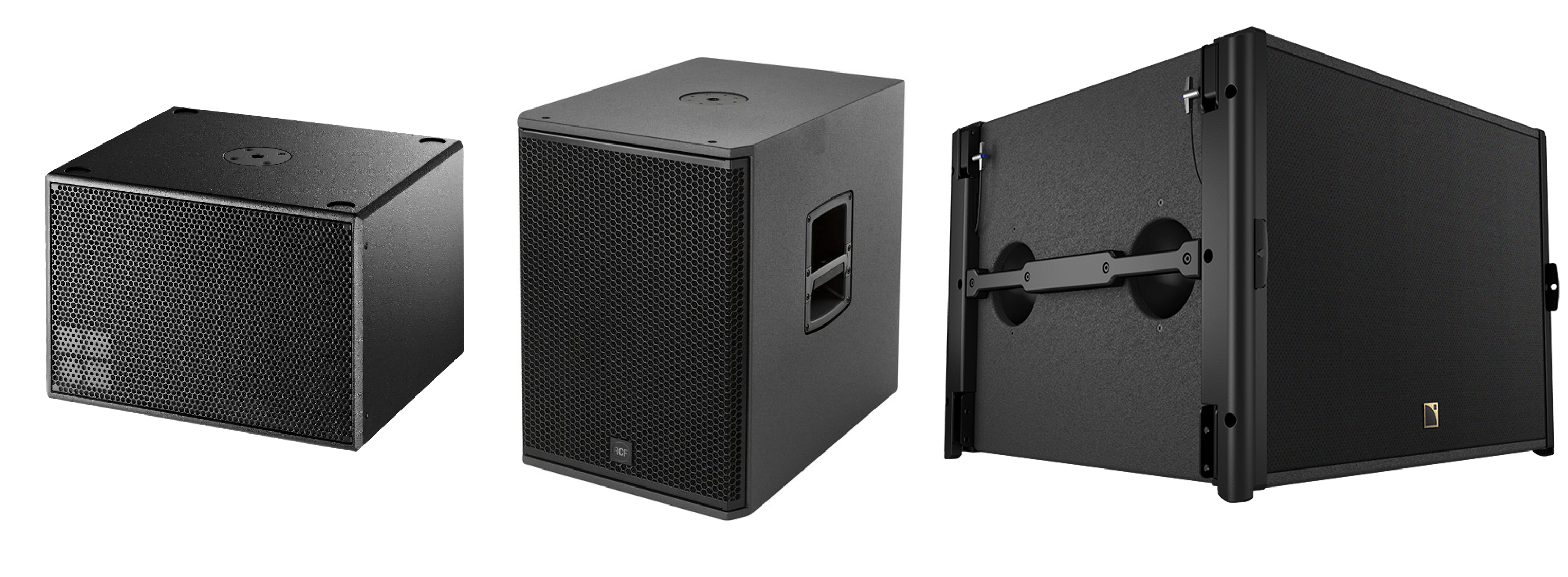
Typical subwoofer models for open-air use, ascending by output: d&B E12X, RCF ART 705 AS, L-Acoustics SB-18 (incl. cardioid switch) (Source: d&B audiotechnik, RCF, L-Acoustics)
If your event is close to residential development / housing, you should still align the stage and loudspeakers so the main radiation does not point toward residential areas. For bass alone, this is often not sufficient, because low frequencies can be clearly perceived behind the stage as well.
A directive sound reinforcement concept (e.g. cardioid subs or sub arrays) can reduce rear and side radiation. With suitable arrangements and settings, the sound field can be controlled more purposefully. Manufacturers provide directivity patterns or recommended setups depending on the system. With subwoofers, the actual effect depends strongly on arrangement, spacing, delay / polarity, and the environment.
Standard case: omnidirectional
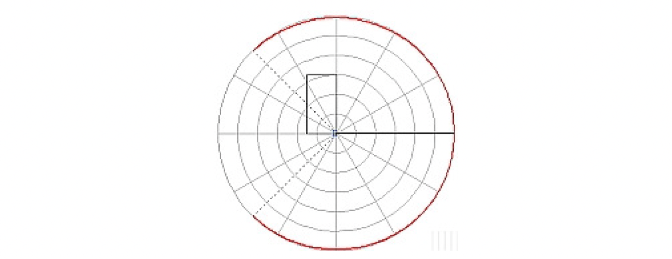
Omnidirectional bass radiation (Source: Electro-Voice)
Sound spreads roughly evenly in all directions. This is typical for single subwoofers in the working range. In noise-sensitive environments, this can lead to clearly audible bass behind the stage, in side areas, or at immission locations (IO).
Sub arrays (broadside)
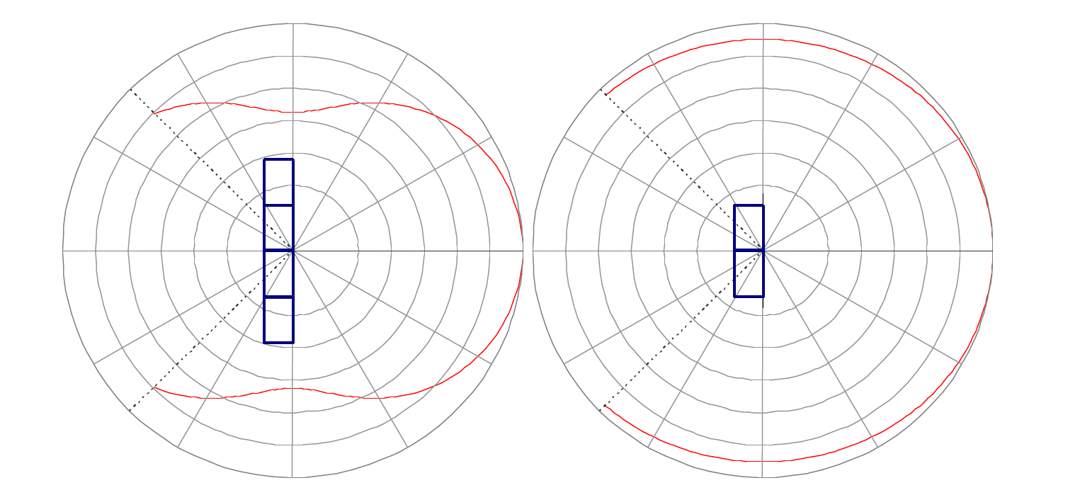
Broadband arrays with 2 and 4 elements at 0.60 Hz. Audience on the right side. (Source: Electro-Voice)
In a broadside array, multiple subwoofers are arranged in a line (often horizontally in front of the stage), without necessarily requiring additional delays or polarity inversion. The main radiation is perpendicular to the line.
Key points:
- Simple setup: Broadside arrays are common in practice and comparatively easy to implement.
- Directivity through length: The longer the array (the more elements), the stronger the focusing in the plane of arrangement.
- More modules mean more potential output: Increasing module count raises not only directivity but also possible output. Level limiting can be sensible or required.
- Reach in the main radiation direction: Sound can carry further in the main direction, which can affect more distant IO more strongly.
With separate left/right sub stacks, interference (lobing / “power alley”) can occur: bass is significantly louder in some areas and weaker in others. This leads to uneven bass distribution across the site. For bass arrays, the distance between individual sources should be adapted to the upper working frequency. As a rule of thumb, spacing should not be greater than half the wavelength of the upper cutoff frequency ().
Example: upper cutoff frequency 100 Hz → → maximum spacing approx. .
Cardioid systems (gradient)
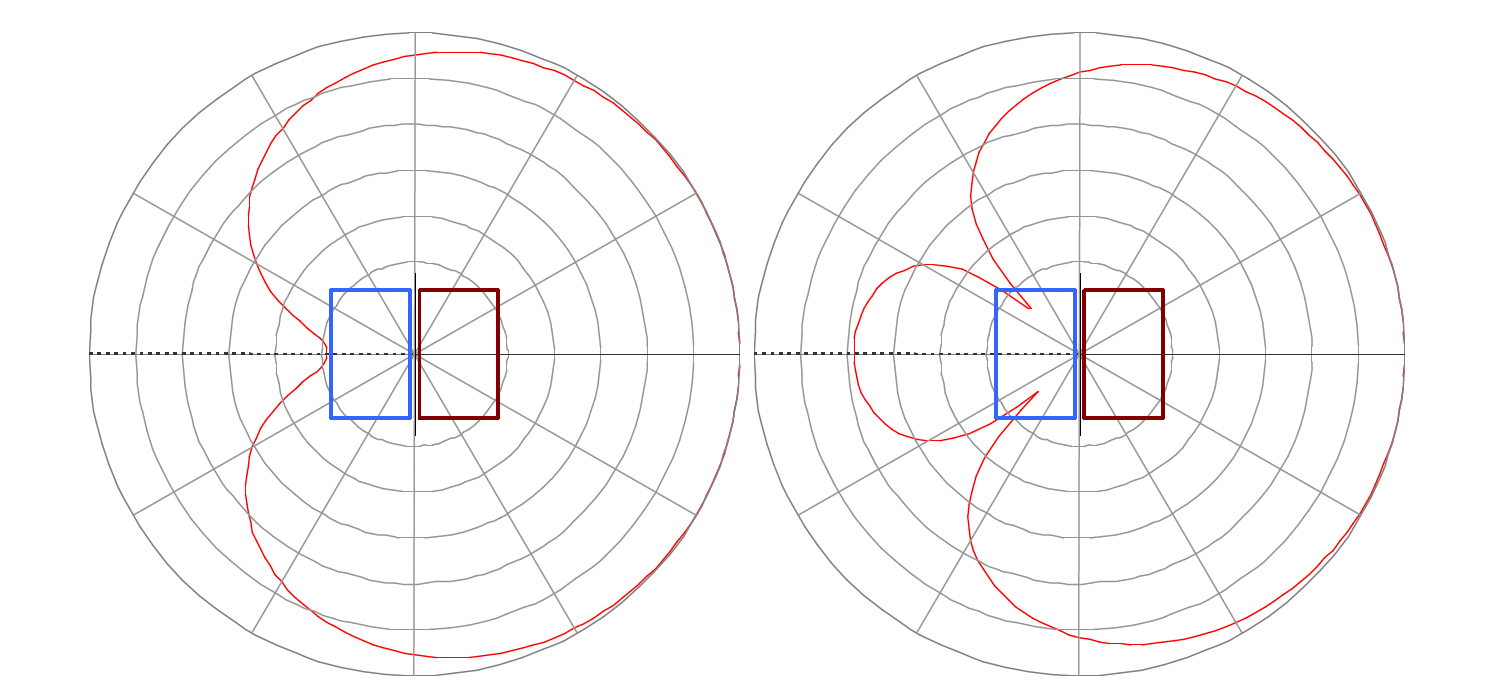
Directivity patterns at 60 Hz. Left: cardioid. Delay = 4.65 ms. Right: hypercardioid, ±135° delay = 3.4 ms. Audience on the right side. (Source: Electro-Voice)
In cardioid or gradient systems, two or more subwoofers are arranged and driven so that unwanted radiation (especially to the rear) is reduced through polarity inversion, delay, and level adjustment. The result is directional radiation, usually cardioid (kidney-shaped) or hypercardioid. Cardioid behaviour can be configured manually or via integrated, switchable cardioid modes that some modern subwoofers already offer.
Typical characteristics:
- Less rear radiation: Behind the loudspeakers, level reductions of about 10–15 dB are often possible in the relevant low-frequency range (depending on setup and frequency range).
- Better for noise-sensitive environments: Can reduce bass on stage and toward residential development / housing.
- Limits due to setup and surroundings: Reflective surfaces nearby (e.g. walls) can significantly reduce directivity.
Commissioning a PA system
Gain staging with limiter
When gain staging with a limiter, the system is limited to a maximum permissible operating level so that the immission guideline values (IRW) are met. Since different IRW apply for day and night, a time-controlled level reduction can be configured. Gain staging can be carried out by accredited measurement bodies. Afterwards, the system is often sealed to prevent manipulation.
This approach is especially suitable for smaller events with relatively constant levels. Weather influences cannot be considered dynamically. The effort is often comparatively low – however, with purely digital signal paths, classic sealing is only possible to a limited extent.
Note: Gain staging is always case-specific. It depends on the surroundings (e.g. residential development / housing / immission locations) and the system used. General presets are therefore not sufficient. More information can be found in the Determining the Permitted Sound Level for Open-Air Events guide.
Procedure
Typical gain-staging process:
- Bring the system to a high or maximum operating level
- Select representative programme material
- Measure the level at a reference measurement location on the audience area
- Measure the level at the relevant immission location (outside or inside the building)
- Calculate the assessment level (measured value, operating time, any surcharges)
- Compare with IRW for day and night
- Determine the permissible operating / emission level
- Set the system to this level (set limiter)
- If required: program a time-controlled level reduction for the night period
- Seal relevant controls and interfaces
Creating noise predictions for PA systems
While the required software for noise predictions is usually very expensive, there are some free alternatives. In particular (only for certified systems by d&B audiotechnik):
Which setup is suitable for my event?
When choosing a suitable PA system, the event type is the key factor. For formats with background music and speech announcements, it can make sense to avoid subwoofers. Low frequencies below about 100 Hz carry far and are often perceived as particularly disruptive in residential areas. The following examples are for orientation.
| Category | Square event (40 m to residential development / housing) | Park event (200 m to residential development / housing) |
|---|---|---|
| Assessment | disruptive (störend) | less disruptive (wenig störend) |
| Goal | high rear attenuation toward residential development / housing, low side radiation | even coverage with sufficient reach; consider surroundings and reflections |
| Main PA (L/R) | 4 line-array modules per side (e.g. d&b Y12 or T10) | 1 top per side (e.g. Loud SM12H) |
| Alignment | arrays slightly toed-in so the main radiation meets just above the audience and side radiation is reduced | align for even area coverage; include environmental reflections |
| Fills | – | 1 front-fill per side (e.g. Loud VHMicro) for near-field |
| Subwoofers | 2 cardioid subwoofers per side (e.g. d&b B4, 15″) | 1 cardioid subwoofer per side (e.g. Loud VH118) |
| Subwoofer configuration | cardioid setup for rear attenuation | cardioid preset or internal DSP / driver configuration for rear attenuation (typically approx. 10 dB) |
| Notes | small vertical coverage angle of the tops (e.g. 10°–15°) for higher directivity; subs approx. 1 m in front of the stage edge to reduce reflections under the stage | balance near-field with front-fills; plan reach and possible long-range impact in the main radiation direction |
Note: The concrete design is always site- and permit-dependent. More information can be found in the Immission Control – Sound & Light guide.
Further information
- Electro-Voice: Subwoofer Arrays - A Practical Guide